

Hold On Matlab App Designer
Simple Example Apps for App Designer
Each of these examples provides instructions on performing tasks frequently used in apps.
-
Display Plot in Axes Components
-
Display Multiple Plots in Axes Component
-
Display Plots in Multiple Axes Components
-
Code Response to Reflect Changing Slider Value
-
Code Response to Button Group Selection
-
Control Component Resize Behavior When App Window Resizes
For more examples, see:
-
Use App Designer to Create a Simple Calculator App
-
Use App Designer to Create a Data Analysis App
-
Use App Designer to Create an App with Instrumentation Controls
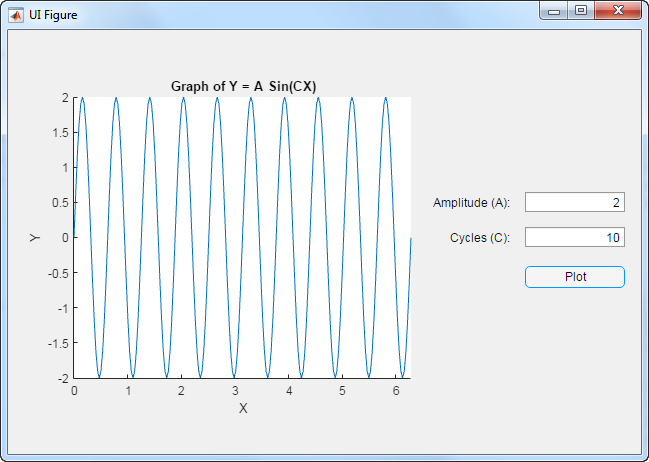
Display Plot in Axes Components
This example shows how to create an app that plots a sine wave with user-specified parameters. When the app user clicks a push button, the sine wave is plotted. The running app looks like this image.
To create the app:
-
In App Designer, from the Component Library on the left, drag a Button component, two Edit Field (Numeric) components, and an Axes (2D) component into the central design area.
-
Arrange the components as shown in the preceding image.
Do not be concerned with component text in this step.
-
In the design area, double-click the text next to the top edit field text and type
Amplitude (A):. -
Double-click the text next to the bottom edit field text and type
Cycles (C):. -
Double-click the button text and type
Plot. -
Select the
Axesand locate the Title property in the Axes Properties panel. Set the title to:Graph of Y = A Sin(CX). -
Above the design area, click Code View.

-
In the Component Browser, to the right of the editor, right-click app.PlotButton and select Callbacks > Add ButtonPushedFcn callback.

-
In the Add Callback Function dialog box, click OK. (Accept the default callback function name.)
-
Add this code to the callback function. These commands use the edit field values to calculate
y. Thenxandyare plotted, and the x-axis limits are adjusted to reflect 0 ≤ x ≤ 2π.x = 0:pi/100:2*pi; c = app.CyclesCEditField.Value; y = app.AmplitudeAEditField.Value * sin(c*x); plot(app.UIAxes,x,y); app.UIAxes.XLim = [0 2*pi];
-
Run the app.
On the toolstrip, click Run.
Save the app when prompted.

Test the app by typing numbers into the Amplitude (A) and Cycles (C) fields. Then click Plot.
Display Multiple Plots in Axes Component
This example shows how to create an app that plots data as specified by the app user's selection from a drop-down component. The running app looks like this image.

To create the app:
-
In App Designer, from the Component Library on the left, drag an Axes (2D) into the central design area.
-
While holding down the Ctrl key, drag a Drop Down into the central design area.
Holding down the Ctrl key as you drag a component from the component library prevents App Designer from adding a label component along with the drop-down component.
-
Resize the axes component, and then arrange the components as shown in the preceding image.
Do not be concerned with axes labels or drop-down component text in this step.
-
Select the axes in the design area. Then, in the Axes Properties panel to the right of the design area, clear the Title, X Label, and Y Label fields.

-
Specify the drop-down component text.
In the central design area, click the drop-down component, and then in the Drop Down Properties panel, set the values as shown. To edit a name in the Items column, double-click it. When you finish making text edits, make sure Line Plot is the selected item.

-
In the design area, resize the drop-down component to make it slightly wider. (Otherwise
Line and Scatter Plotwill be clipped in the running app.)Tip To make the drop-down component the same size as shown in this example, on the toolstrip Canvas tab, select Show resizing hints.
 .
. When you widen the drop-down component, App Designer displays the width in pixels. The width used in this example is 110 pixels.

-
View the code created for your app.
Above the design area, click Code View.
-
Add a private property to hold plotting data for your app.
On the Editor tab, click the Property down arrow and select Private Property.

-
In the code editor, replace the highlighted word
Propertywith the property name,xdata.When you refer to the property in a function, use dot notation,
app.xdata. -
Add another private property,
ydata. -
Create a
StartupFcncallback to specify the plot that you want to appear when the app first opens. On the Editor tab, click Callback. In the Add Callback Function dialog box, select the following options and click OK.
-
App Designer places the cursor in the body of the empty callback function. Add this code to
startupFcn:app.xdata = linspace(0,3*pi,10); app.ydata = cos(app.xdata) + rand(1,10); plot(app.UIAxes,app.xdata,app.ydata);
-
Create a callback to control what the app does when an app user makes a selection from the drop-down component.
In the Component Browser, right-click app.DropDown and select Callbacks > Add ValueChangedFcn callback.

-
In the Add Callback Function dialog box, click OK. (Accept the default callback function name.)
App Designer adds sample code
value = app.DropDown.Value;to theDropDownValueChangedfunction. -
Update the callback code so it appears as follows. This code gets the option that the app user selected from the drop-down component, and then plots the data accordingly. The
holdfunction keeps the scatter plot from replacing the line plot.value = app.DropDown.Value; if strcmp(value,'Line Plot') plot(app.UIAxes,app.xdata,app.ydata); elseif strcmp(value,'Scatter Plot') scatter(app.UIAxes, app.xdata, app.ydata); else plot(app.UIAxes,app.xdata,app.ydata); hold(app.UIAxes,'on'); scatter(app.UIAxes, app.xdata,app.ydata); hold(app.UIAxes,'off'); end
-
Run the app.
On the Editor tab, click Run.
Save the app when prompted.
Test the app by selecting different options from the drop-down component.
Display Plots in Multiple Axes Components
This example shows how to create an app that accepts input parameters and plots data in two axes. The parameters define a time-varying and frequency-varying signal. One plot displays the data in the time domain. The other plot displays the data in the frequency domain. Both plots update when the app user clicks the push button. The running app looks like this image.

To create the app:
-
In App Designer, from the Component Library on the left, drag the components described in the following table into the central design area. Arrange the components as shown in the preceding image. Use the property sheet to the right of the design area to set component property values. By default, a label component is added when you drag an edit field into the design area. The Label column indicates the text to use for the label component associated with each edit field component that you add.
Component Label Property to Set Axes (2D) Not applicable Title: Frequency Axes (2D) Not applicable Title: Time Edit Field (Numeric) f1 Maximum: 500 Edit Field (Numeric) f2 Maximum: 500 Edit Field (Text) t Not Applicable Button Plot Text: Plot -
Add a callback function for the Plot button.
In the design area, right-click the Plot button and select Callbacks > Add ButtonPushedFcn callback.

-
In the Add Callback Function dialog box, click OK. (Accept the default callback function name.)
App Designer opens code view.
-
Get the input values, perform calculations, and plot the data in the appropriate axes.
Add this code to the
PlotButtonPushedcallback:% Get app user input f1 = app.f1EditField.Value; f2 = app.f2EditField.Value; t = str2num(app.tEditField.Value); % Calculate data x = sin(2*pi*f1*t) + sin(2*pi*f2*t); y = fft(x,512); m = y.*conj(y)/512; f = 1000*(0:256)/512; % Create frequency plot in proper axes plot(app.UIAxes,f,m(1:257)); app.UIAxes.XMinorTick = 'on'; % Create time plot in proper axes plot(app.UIAxes2,t,x); app.UIAxes2.XMinorTick = 'on';
-
Run the app.
On the toolstrip, click Run.
Save the app when prompted.
Test the app by trying the various app controls in the running app.
-
The numeric edit fields,
f1andf2, display an error message if you enter a nonnumeric value or one that falls outside the limits that you set.This automatic input validation is an advantage to using a numeric edit field, rather than a text edit field to get numeric input.
-
The edit field for the time vector does not prevent you from entering an invalid vector. To handle invalid time vector values, define a
ValueChangedFcncallback function for theapp.tEditFieldcomponent. Then code it to determine if the app user's input is valid.
Code Response to Reflect Changing Slider Value
This example shows how to create an app that displays a slider value in a semicircular gauge. The semicircular gauge is continuously updated to reflect the current slider value as the app user moves it. (Another example, Create Simple App Using App Designer updates the semicircular gauge only when the app user releases the mouse button from the slider.) The running app looks like this image.

To create the app:
-
In App Designer, while holding down the Ctrl key, drag a Slider and a Semicircular Gauge from the Component Library into the central design area. Arrange the components as shown in the preceding image.
Tip Holding down the Crtl key as you drag a component from the component library prevents App Designer from adding a label component along with the component you drag in.
-
Specify a name to appear in the app title bar.
In the Component Browser, click
app.UIFigure, and then in the UIFigure Properties panel change the Title field toTrack Slider.
-
Select
app.Gaugein the Component Browser. Then in the Gauge Properties panel, click More Properties in the Scale section. Edit the table as follows:-
Click + to add a color.
-
Click the color patch in the left column to open the color picker. After selecting a new color, click away from the color picker to close it.
-
Set Start to
80, and set End to100.

-
-
In the central design area, right-click the slider and select Callbacks > Add ValueChangingFcn callback.

-
In the Add Callback Function dialog box, click OK. (Accept the default callback function name.)
Code view opens.
-
Code the callback to update the edit field when the app user drags the slider.
When the app user drags the slider, MATLAB® generates
eventdata and stores it in the slider eventValueproperty. You can query the event data using dot notation.Replace the default
SliderValueChangingcallback code,changingValue = event.Value;, with the following code:app.Gauge.Value = event.Value;
-
Run the app.
On the toolstrip, click Run.
Save the app when prompted.
Test the app by performing these steps:
-
Drag the slider to a new value.
As you do so, the semicircular gauge is continuously updated to display the current slider value.
-
Click the slider.
The semicircular gauge is updated to display the new slider value.
Code Response to Button Group Selection
This example shows how to create an app that changes the color of a lamp based on which radio button the app user selects. The running app looks like this image.

To create the app:
-
In App Designer, drag a Radio Button Group and a Lamp from the Component Library into the central design area. By default, a label is added with the lamp. Arrange and customize the components as shown in the preceding image and described in this table. Change each component's label text by double-clicking each label on the canvas:
-
Set the button group label to
Indicator. -
Set the top radio button label to
Stop. -
Set the middle radio button label to
Caution. -
Set the bottom radio button label to
Go. -
Set lamp label to
Status.
-
-
Select
app.CautionButtonin the Component Browser. Then locate the Selected check box in the Button Properties panel and check it. Checking this box makes the Caution button the default selection in the app. -
Above the design area, click Code View.
-
In the Component Browser, right-click app.IndicatorButtonGroup, and then select Callbacks > Add SelectionChangedFcn callback.

-
In the Add Callback Function dialog box, click OK. (Accept the default callback function name.)
Code view opens.
-
Specify code to determine which radio button is selected, and then set the lamp color accordingly.
Replace the default code in the
IndicatorButtonGroupSelectionChangedfunction with this code. The code changes the lamp color depending on the radio button selected by the app user.switch app.IndicatorButtonGroup.SelectedObject case app.GoButton app.StatusLamp.Color = 'green'; case app.CautionButton app.StatusLamp.Color = 'yellow'; case app.StopButton app.StatusLamp.Color = 'red'; end
-
Run the app.
On the toolstrip, click Run.
Save the app when prompted.
Test the app by selecting each radio button.
Control Component Resize Behavior When App Window Resizes
This example shows how to code the callback for an UI figure window containing a slider so that when the app user resizes the window, the slider size changes and remains centered in the window.
By default, components resize when the app user resizes the app window. If you code the UI figure SizeChangedFcn callback, your callback code takes precedence.
Note: Only consider coding the SizeChangedFcn callback when you want components to resize, but do not like the default resize behavior.
The running app looks like this image

To create the app:
-
In App Designer, hold down the Ctrl key as you drag a Slider from the Component Library into the central design area.
Holding down the Ctrl key prevents a label component from being added with the slider.
-
Center the slider in the design area.
As you move the slider, App Designer displays hints to help you center the component.

-
Above the design area, click Code View.
-
In the Component Browser, right-click app.UIFigure, and then select Callbacks > Add SizeChangedFcn callback.

-
In the Add Callback Function dialog box, click OK. (Accept the default callback function name.)
-
Update the callback code as shown here.
position = app.UIFigure.Position; app.Slider.Position = [30, (position(4)-6)/2, position(3)-60, 6];
This code gets the UI Figure window width and height after a resize operation and updates the location and size of the slider to keep it centered in the window. The slider will be 30 pixels from the left and right sides of the window. The code subtracts the slider height (6 pixels) from the window height and divides by 2. The code subtracts 60 from the window width to account for 30 pixels on either side of the slider.
-
Run the app.
On the toolstrip, click Run.
Save the app when prompted.
Test the app by resizing the UI Figure window.
Note: Code you specify for the SizeChangedFcn callback takes precedence over the resize behavior you select in design view with the UIFigure Properties panel.

Related Examples
- Create Simple App Using App Designer
Was this topic helpful?
Hold On Matlab App Designer
Source: https://lost-contact.mit.edu/afs/inf.ed.ac.uk/group/teaching/matlab-help/R2016b/matlab/creating_guis/simple-app-designer-example-apps.html
Posted by: towerdenteoffores.blogspot.com
0 Response to "Hold On Matlab App Designer"
Post a Comment